


Published on Apr 02, 2024
The pulsed electro acoustic analysis (PEA) can be used for space charge measurements under dc or ac fields. The PEA method is a non-destructive technique for profiling space charge accumulation in polymeric materials. The method was first proposed by T.Takada et al. in 1985. The pulsed electro acoustic (PEA) method has been used for various applications.
PEA systems can measure space charge profiles in the thickness direction of specimen, with a resolution of around 10 microns, and a repetition rate in the order of milliseconds. The experimental results contribute to the investigation of the charge transport in dielectrics, aging of insulating materials and the clarification of the effect of chemical properties on space charge formation. PEA method can measure only net charges and does not indicate the source of the charge.
Various space charge measurement techniques are thermal step, thermal pulse, piezoelectric pressure step, and laser induced pressure pulse, the pulse electro acoustic method. In the thermal step method, both electrodes are initially in contact with a heat sink at a temperature around -10 degrees Celsius. A heat source is then brought into contact with one electrode, and the temperature profile through the sample begins to evolve towards equilibrium consistent with the new boundary conditions.
The resulting thermal expansion of the sample causes a current to flow between the electrodes, and application of an appropriate deconvolution procedure using Fourier analysis allows extraction of the space charge distribution from the current flow data. This technique is particularly suited for thicker samples (between 2 and 20 mm). Next is the thermal pulse technique. The common characteristic is a temporary, non -destructive displacement of the space charge in the bulk of a sample created by a traveling disturbance, such as a thermal wave, leading to a time dependent change in charge induced on the electrodes by the space charge. Compression or expansion of the sample will also contribute to the change in induced charge on the electrodes, through a change in relative permittivity. The change in electrode charge is analyzed to yield the space charge distribution.
Thermal pulse technique yields only the first moment of the charge distribution and its first few Fourier coefficients. Next is laser induced pressure pulse. A temporary displacement of space charge can also be achieved using a pressure pulse in the form of a longitudinal sound wave. Such a wave is generated, through conservation of momentum, when a small volume of a target attached to the sample is ablated following absorption of energy delivered in the form of a short laser pulse. The pressure pulse duration in laser induced pressure pulse measurements depends on the laser pulse duration and it can be chosen to suite the sample thickness, ie, thinner the sample the shorter should be the laser pulse.
Space charge measurement has become a common method for investigating the dielectric properties of solid materials. Space charge observation is becoming the most widely used technique to evaluate polymeric materials for dc-insulation applications, particularly high-voltage cables. The presence of space charges is the main problem causing premature failure of high-voltage dc polymeric cables. It has been shown that insulation degradation under service stresses can be diagnosed by space charge measurements.
The term" space charge" means uncompensated real charge generated in the bulk of the sample as a result of (a) charge injection from electrodes, driven by a dc field not less than approximately 10 KV/mm, (b) application of mechanical/thermal stress, if the material is piezoelectric/ pyroelectric (c) field-assisted thermal ionization of impurities in the bulk of the dielectric.
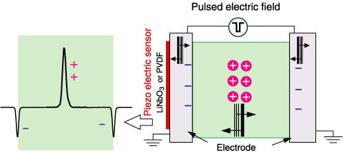
Figure shows the principle of the PEA method.
When a pulsed electric field is applied to a specimen that has internal charge, the pulsed electric field and charges (internal charges and induced charges on the electrodes) generate forces, resulting in acoustic waves. The acoustic waves propagate in the specimen and are detected by a piezoelectric sensor made with poly vinylidene fluoride (PVDF) or lithium niobate (LiNbO3) attached to the electrode; an oscilloscope observes them. The amplitude of the signal is proportional to the charge quantity, and the delay indicates the distance from the sensor, ie, the position of the charge. In this manner, the space charge distribution is measured quantitatively and nondestructively.
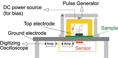
Figure shows basic set-up of the PEA method.
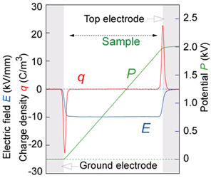
Figure shows example of profiles obtained by the PEA.
Here shows an example of charge, electric field and potential distributions obtained by applying a dc bias voltage to a polystyrene sheet. Because the specimen does not contain internal charge, only induced charges on the electrode were observed as shown by red line q. By integrating the charge profile, the electric field distribution is obtained as the blue line E; by integrating the field, the potential distribution is obtained as the green line P. these three profiles give the fundamental performance of the individual system.
A 3-D PEA system can observe space charge distribution in 3-D of dielectric materials safely and nondestructively. There are two types of 3-D PEA system. They are acoustic lens method and multisensor method. In the case of acoustic lens method the measurement time was reduced, and the resolution was significantly improved. In the case of multisensor method it can use a sensor array to collect space charge profiles in the thickness direction from many points at once.
With this lens, only acoustic waves generated at the focus can be detected by the piezoelectric sensor. By moving the acoustic lens unit, the space charge profiles in the thickness direction can be collected in sequence. After collecting all of the profiles in the observation area, signals are displayed as lateral distributions. It takes about 2 sec to observe a reasonable profile from one point. The measurement time is determined by the number of detection points. Obviously, if the charge profile changes rapidly, the lateral profile is affected by the time dependence.
Here is an example of 3-D space charge measurement obtained by two polystyrene sheets with an evaporated electrode ‘letter C’ on one sheet. Positive charge (red) appeared at the interface of the two polystyrene sheets having the shape of the letter C. negative-induced charges (blue) were observed at the positions of the two electrodes. Because there is no internal charge, the other areas were observed as neutral (green).
These profiles revealed that the resolution in the lateral direction was approximately 200 micrometer. The improvement of resolution is ongoing.
The specimen was a metal-base printed circuit board with an insulation layer of epoxy resin on a thick aluminum base plate. The anode was a copper electrode and is known to cause ionic migration under dc electric field at high temperature and high humidity. Space charge profiles were measured and compared with the copper distributions observed by electron probe microanalysis (EPMA) during an aging test. The space charge profile after aging showed that a conductive region was formed near the anode; EPMA analysis clearly showed the copper distribution in the same region. These results prove that the PEA can monitor ion migration.
When a dc voltage was applied to a specimen, a positive (red) signal appeared at the anode as well as inside the insulation, particularly at the fringe of the anode, and not below the center part of the electrode. This suggests that the migration occurs dominantly at the edge of the anode. Negative charge (blue) appeared at the ground electrode, and the other part was neutral (green).
Although the ion migration phenomenon has been studied for a long time, it is becoming a more serious problem because of the severe requirements from the electronics and telecommunication industries. The 3-D space charge measurement should provide useful information for examining the ion migration phenomenon and should contribute to the investigation of its mechanism.
The multi-sensor technique for 3-D space charge measurement is ‘the normal PEA’ with many acoustic sensors. The set up has 10 sensors attached to the bottom electrode, and signals are detected by the sensors at the same time when a voltage pulse is applied. Each sensor is a PVDF film (2 mm wide, 3mm long, 9 micrometer thick), and the sensors are placed at 3mm intervals. A coaxial switch is used to record signals from the sensors separately. The resolution in the lateral direction is determined by the distance between sensors, and the distance was about 3mm. Because the sensors are placed in a line, the current multi sensor PEA gives space charge profiles in two dimensions. By placing sensors at the nodes of a grid, 3-D profiles will be obtained.
The acoustic lens method can measure 3-D space charge profiles precisely when the profiles do not change rapidly, so that it would be suitable for monitoring long-time aging phenomena such as ion migration. At the same time, there are users who appreciate the rapid measurement capability of the multi sensor method though it results in a rough 3-D profile.
| Are you interested in this topic.Then mail to us immediately to get the full report.
email :- contactv2@gmail.com |
